Inhaltsverzeichnis
Rough draft for a Zigbit evaluation board
Goal:
The goal of this project is to supply a PCB, which connects the Zigbit module (ATZB-24-A2) with a Jtag Connector and with an io.Mate.USB1. Furthermore, all the PINs of the Zigbit module should all be routed to Dual-Line-Pins.
The Zigbit module has to be connected as it is shown in (2.) On page 3-13.
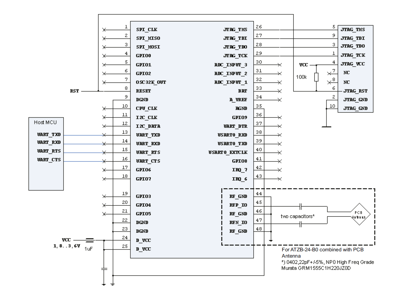
However, without the PCB Antenna in the right corner. All the Pins marked with an X should be routed to Dual-Line-Pins. The Jtag Connector has to be soldered separately and must fit to the Jtag Connector from the Jtag MKII ((3.) Page 3, 10 Dual-Line-Pins, 2.54mm grid)
The ioMate.USB1 (1.) needs to be connected to the PCB via a standard DIL16 pin header with 2.54mm grid. Four (DIL16) pins have to be cut off underneath the USB mini-B connector, before assembly.
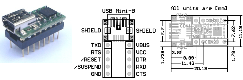
The USB bus supply voltage VCC from the ioMate.USB1 should be connected to pin 24 of the Zigbit module and to VCC of the JTAG connector. In addition, the GND from the ioMate.USB1 has to be connected to pin 9 or 35 of the Zigbit module. For battery use, it might be reasonable that the VCC and Ground pins of the Zigbit module are routed out to Dual Line Pins, too. For switching between battery and Usb power a jumper should be soldered.
To enable debugging, it is necessary to connect the RXD pin from the ioMate.USB1 with the TXD Pin 13 of the Zigbit module.
For future use, it may be useful to connect the TXD pin from the ioMate.USB1 with the RXD Pin 14 of the Zigbit module. Maybe we use Handshaking in future, so it is required, that RTS of one device connects to CTS of the other, and vice versa.
Reference documents:
- (1.) Data sheet ioMate.USB1 http://lib.chipdip.ru/315/DOC000315066.pdf
- (2.) Data sheet Zigbit module http://www.atmel.com/Images/doc8226.pdf
- (3.) Data sheet Jtag MKII http://www.atmel.com/Images/doc2562.pdf
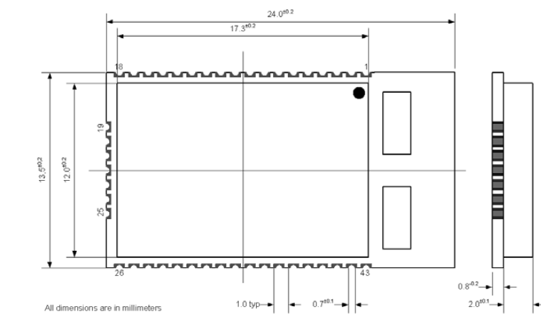
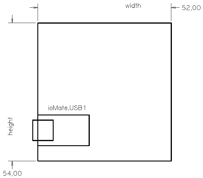
Pcb dimensons:
- The dimensons should not exceed 54mm height and 52mm width.
- The direction of the USB-B plug of the ioMate.USB1 has to point to one of the height sides.
Bsp.
Sugesstions for Revision 2 - lessons learnt from first prototype
- include a power LED, maybe also a send/receive indication directly on the board
- Rx/Tx on the Zigbit Module are reversed!
- include a Reset-Button on the board
- use a small JTAG-Interface, just as on the ATMEL-Raven
- move the Battery/VCC jumper-switch out of the way (currently to close to the JTAG), needs to be accessible for re-programming
- Do we really need to route all the pins from the Zigbit/ioMate? (Which ones are the most usefull/useless?)